In the previous post we configured the Database Availability Group of Exchange 2010. In this post I will show you how to configure Exchange 2010 RPC Client Access Array. Previous Exchange versions (Exchange 2000/2003) did not support to the use the front-end server by internal MAPI clients. They were connected directly to internal Back-End servers via MAPI over RPC. With the introduction of Exchange server 2007 this limitation has decreased significantly. Client Access Server worked for most protocols except MAPI clients.
With Exchange Server 2010 all protocols should go through the Client Access Server and cannot connect to Mailbox servers by MAPI clients directly. This has been done by introducing a new Client Access Server(CAS) service known as the RPC Client Access service.
To configure Exchange Server 2010 CAS array, you should follow the five steps mentioned bellow.
- You must configure internal DNS entry for the name of the CAS array. This name must be unique for the internal network.
- You must configure Network Load Balancing. In this case i use Windows Network Load Balancing technology.
- Create the new Client Access Array.
- Configure a mailbox database to use Cas Array
- Verify the Autodiscover services is working with CAS Array. (This step is optional, but it would be good to verify this)
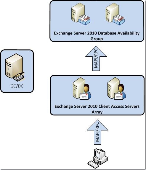
Architecture of Clients connecting through a CAS array to a mailbox database
Step 1 – Configure Internal DNS
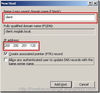
1) Open DNS services manager in Administrative tools and add new a “A Record(Host)” for the Client Access Server array. I used “Client” as CAS Array name and 200.200.201.120 as IP Address of CAS Array. See figure 1.
Figure 1
Step 2 – Configure Network Load Balancing for the Client Access Server Array.
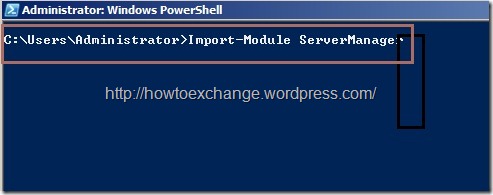
2.1) You must install Windows Network Load balancing feature in CAS servers, where you are supposed to configure CAS array. Run below commend in Powershell. See figure 2 and 3.
Import-Module ServerManager
Add-WindowsFeature NLB
Figure 2: Running “Import-Module ServerManager”
Feature 3: Running “Add-WindowsFeature NLB”
You will see the screen below after successful NLB installation. See figure 4.
Figure 4.
2.2) Start Network Load Balancing Manager by following – Start / All Programs / Administrative Tools/ Network Load Balancing Manager. See figure 5.
Figure 5: Network Load Balancing Manager.
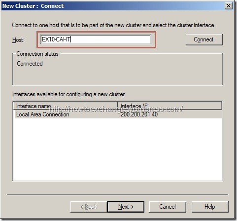
2.3 ) Click Cluster –> New to create a new NLB Cluster. In the Host section add Netbios name or ip address of the first Client Access Server. In this scenario first CAS Netbios name is “EX10-CAHT”. Then click Next. See figure 6.
Figure 6.
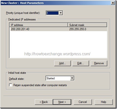
2.4) Here you can see the parameters of the NLB cluster. Leave it as default. Click Next. See figure 7.
Figure 7: New Cluster: Host Parameters
2.5) Then you should add the IP Address of the CAS array. All clients should connect via this ip address and you must give the IP Address that you added in DNS manager during A Record creation. In this scenario it was 200.200.201.120. Then click ok and next. See figure 8.
Figure 8: Adding IP Address for CAS Array.
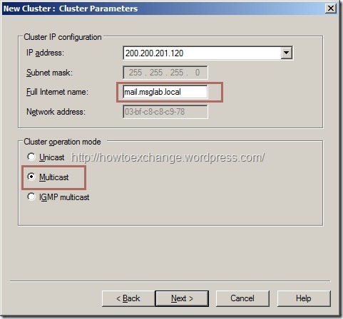
2.6) In this screen you must add Full Internet Name and Select Cluster Operation Mode. Give the internal FQDN for the Full Internet Name and Select Multicast as shown below. See Figure 9.
Figure 9:- Adding FIN and selecting operating mode.
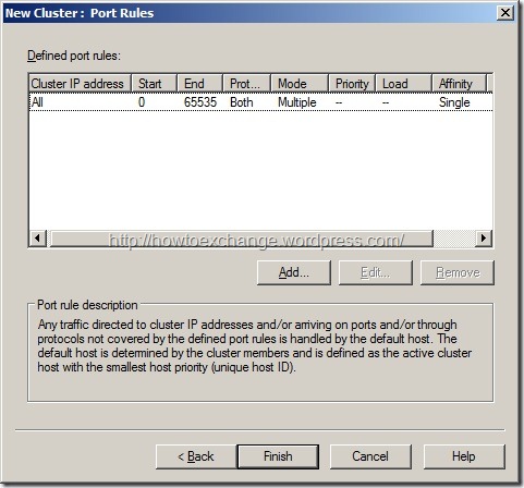
2.7) Then appears the Port Rules screen. Leave it as default. Click Finish. See figure 10.
Figure 10: Port Rules.
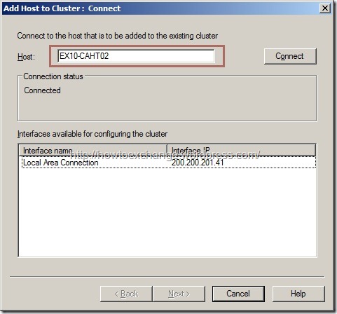
2.6) At this point we have created a new NLB cluster. Then we must add the next Client Access Server(S) to the NLB. Right click the cluster name and click Add Host to Cluster. In this scenario our second CAS server is EX10-CAHT02. Then click Next and Finish. See figure 11 and 12.
Figure 11
Figure 12: Adding Second node’s Netbios name.
Now you can see Windows NLB has been created. See Figure 13.
Figure 13: NLB Manager
Step 3 – Create Client Access Server Array
3.1) We don’t have any pre-Created CAS arrays in this Organization. But would be better to check is there are any pre-created CAS Arrays. Run below command. if you didn’t create a CAS Array before, you will get nothing . See figure 14.
Get-ClientAccessArray
Figure 14.
3.2) Then you should create new Client Access Array. Run below Cmdlet in EMS. See Figure 15.
Figure 15: Creating new CAS Array.
Now we have finished creating an NLB and a CAS array. Then we must associate databases with this CAS Array.
Step 4 – Adding Mailbox Databases to Client Access Server Array
Now we have come to the final step, that is need to add mailbox database to the Client access server array.
4.1) Use below CMDLet to add mailbox database to CAS array. Here we can add all mailbox databases at once as shown as shown below. See Figure 16.
Get-MailboxDatabase | Set-MailboxDatabase -RPCClientAccessServer “Client.msglab.local”
Figure 16 : Adding MailBox databases to the CAS Array.
Step 5 – Configuring Outlook 2010 using Auto Discover
Now when Outlook connects to the Exchange Server, the CAS Array name Appears as client.msglab.local. See figure 17.
Figure 17: Account Information of Outlook
You can see below actual connections made by Outlook. See figure 18.
Figure 18: Connection Status
Note- Client Access Array is only used by MAPI Clients to connect MailBox ,Public Folders and Active Directory only. You must use Windows NLB or another 3rd party NLB solution to load balance Active Sync, AutoDiscover and Availability Services.
